
How to resurface an Aluminum Head For a MLS head gasket.


Thread Starter
|
Member
Joined: Dec 2009
Posts: 52
Likes: 0
From: Pensacola Fla
How to resurface an Aluminum Head For a MLS head gasket.
I use a Comec Auto I 1000 High Speed Milling Machine with CBN insert for Cast Iron OR a PCD Insert for Aluminum Heads
This machine is double adjustable, I can adjust the spindle speed and the table travel speed to achieve the surface finish that is required.
Auto I 1000 CBN Surfacer
The first thing to do is check the valve cover surface for any burrs and remove them.
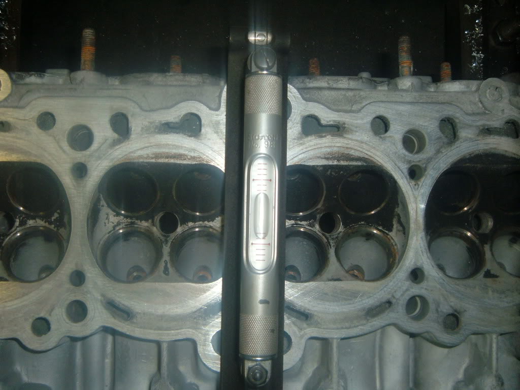
Next is to mount the head in the machine and check the level of the head in both directions.
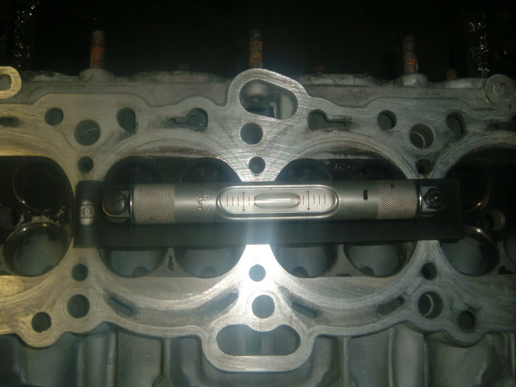
Then the other way, this head was not out that bad from the last time it was milled.
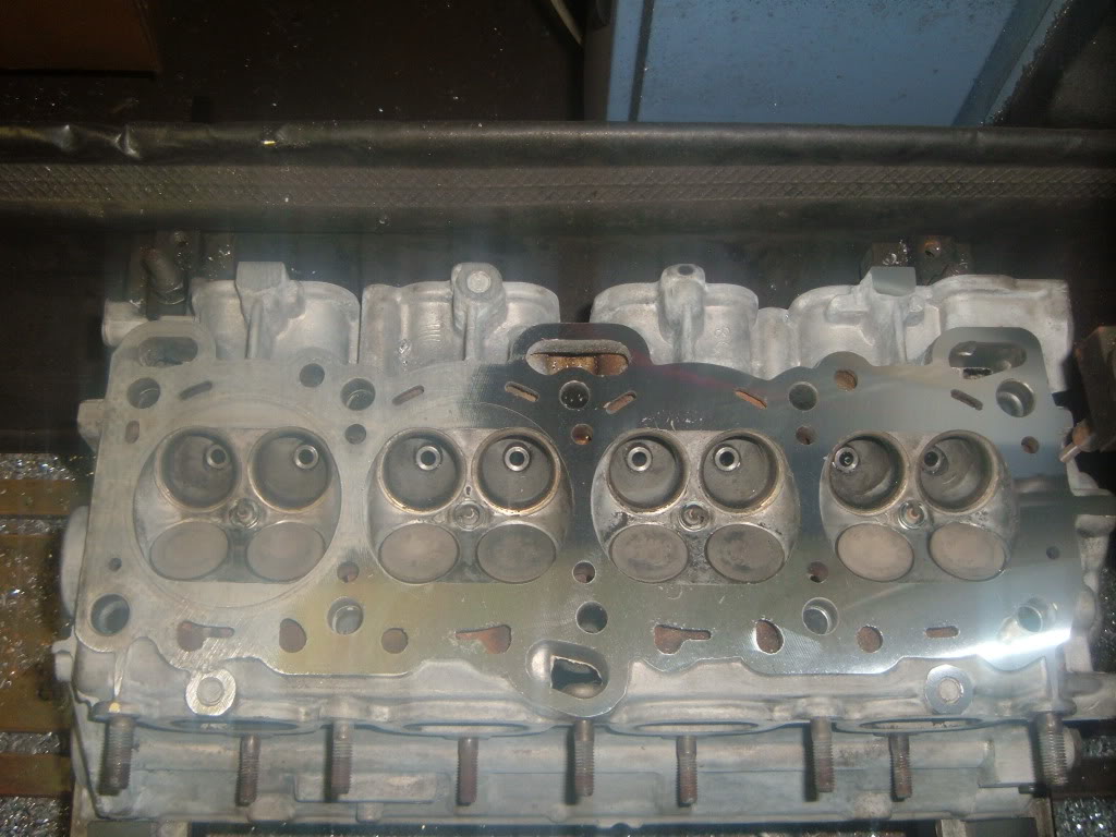
I did a �getting to know you� pass of .002 to see how square the head was. This was done on a faster setting.
Notice the upper and left side of the head is dull, this is a low spot. The head was not index properly and did not maintain a proper �square� to the valve cover surface.
I made another cut of .003, I sped up the cutter, and slowed the table speed.
This is the end result.
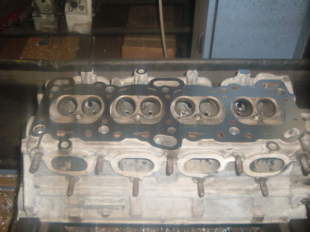
Another different view.
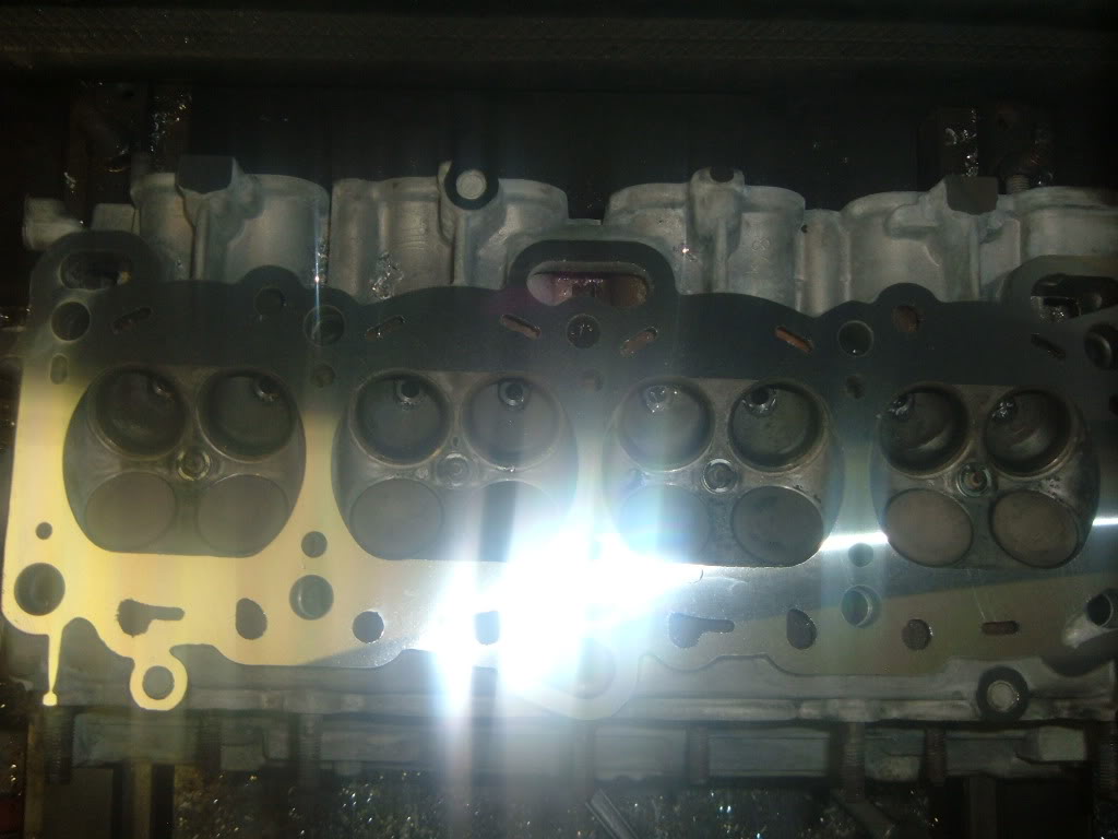
Now with a proper surface, and the head re-squared, The customer will have no issues with a MLS gasket sealing, and also having a closer to equal combustion chamber size.
I use a Comec Auto I 1000 High Speed Milling Machine with CBN insert for Cast Iron OR a PCD Insert for Aluminum Heads
This machine is double adjustable, I can adjust the spindle speed and the table travel speed to achieve the surface finish that is required.
Auto I 1000 CBN Surfacer
The first thing to do is check the valve cover surface for any burrs and remove them.
Next is to mount the head in the machine and check the level of the head in both directions.
Then the other way, this head was not out that bad from the last time it was milled.
I did a �getting to know you� pass of .002 to see how square the head was. This was done on a faster setting.
Notice the upper and left side of the head is dull, this is a low spot. The head was not index properly and did not maintain a proper �square� to the valve cover surface.
I made another cut of .003, I sped up the cutter, and slowed the table speed.
This is the end result.
Another different view.
Now with a proper surface, and the head re-squared, The customer will have no issues with a MLS gasket sealing, and also having a closer to equal combustion chamber size.

Banned
Joined: Dec 2011
Posts: 2,633
Likes: 0
From: Canada
Do you know how much of a difference?

Too take even more off if you want you should check piston to valve clearance. How much compression can you go without tuning?
However, you obviously can't go beyond valve seats. You probably have to remove it from the block
Found this great article on piston to valve clearance:
So, how much clearance is enough? A safe rule of thumb is .080-inch for intake valves and .100-inch for exhaust, which requires a little more clearance because of the increased heat factor. Experts also suggest adding .030 to each valve if the engine is equipped with aluminum rods as they tend to stretch more than steel.
Advancing or retarding the camshaft will also affect P2V clearance. Advancing the cam helps build low-end torque but it also decreases the intake P2V clearance while increasing exhaust clearance. It’s the just the opposite for retarding cam timing when higher RPM power is desired–increased intake P2V clearance with decreased exhaust clearance.
Other factors that affect P2V clearance include head gasket thickness, valve diameter and angle, piston design, cylinder-block deck height, push-rod flex and valve-seat recession.
FOR MORE INFO FROM THAT ARTICLE: ClickMe
I will be posting this on http://markenperformance.com/ next week, news section.
Last edited by UseYourNoggin; Feb 1, 2013 at 10:51 AM.
Thread Starter
|
Member
Joined: Dec 2009
Posts: 52
Likes: 0
From: Pensacola Fla
The math to figure static Compression Ratio is fairly simple.
V1 + V2 + V3 + V4 + V5 / V1 + V2 + V3 + V4
V1 = Cylinder head CC
https://www.mazdaforum.com/forum/gen...71/#post103279
V2 = head gasket volume
V3 = piston to deck volume
V4 = piston volume
V5 = swept volume of the cylinder.
A general rule of thumb is for every .006-.007 milled from the head will close the combustion camber 1cc
The P2V clearance you listed is a safe value. I am happy when I have .040 on the intake and .060 on the exhaust on a steel rod engine.
Also over sized valve heads (big valve) run the risk of contact on the outer edges of the valve relief on stock pistons.
But claying the pistons during the "dry" build of engine will give the clearances.
If the P2V is too close, or the edges of piston valve reliefs are an issue, the pistons can be fly cut, or a touch with a die grinder can solve the issue.
Banned
Joined: Dec 2011
Posts: 2,633
Likes: 0
From: Canada
The math to figure static Compression Ratio is fairly simple.
V1 + V2 + V3 + V4 + V5 / V1 + V2 + V3 + V4
V1 = Cylinder head CC
https://www.mazdaforum.com/forum/gen...71/#post103279
V2 = head gasket volume
V3 = piston to deck volume
V4 = piston volume
V5 = swept volume of the cylinder.
A general rule of thumb is for every .006-.007 milled from the head will close the combustion camber 1cc
The P2V clearance you listed is a safe value. I am happy when I have .040 on the intake and .060 on the exhaust on a steel rod engine.
Also over sized valve heads (big valve) run the risk of contact on the outer edges of the valve relief on stock pistons.
But claying the pistons during the "dry" build of engine will give the clearances.
If the P2V is too close, or the edges of piston valve reliefs are an issue, the pistons can be fly cut, or a touch with a die grinder can solve the issue.
V1 + V2 + V3 + V4 + V5 / V1 + V2 + V3 + V4
V1 = Cylinder head CC
https://www.mazdaforum.com/forum/gen...71/#post103279
V2 = head gasket volume
V3 = piston to deck volume
V4 = piston volume
V5 = swept volume of the cylinder.
A general rule of thumb is for every .006-.007 milled from the head will close the combustion camber 1cc
The P2V clearance you listed is a safe value. I am happy when I have .040 on the intake and .060 on the exhaust on a steel rod engine.
Also over sized valve heads (big valve) run the risk of contact on the outer edges of the valve relief on stock pistons.
But claying the pistons during the "dry" build of engine will give the clearances.
If the P2V is too close, or the edges of piston valve reliefs are an issue, the pistons can be fly cut, or a touch with a die grinder can solve the issue.


Thread
Thread Starter
Forum
Replies
Last Post
mxteam
Mazda Protege
5
Oct 24, 2007 06:52 AM