
2 Liter engine


Senior Member
Joined: Jan 2006
Posts: 3,183
Likes: 0
From: Aberdeen, MD
1. Remove the plug hole plate.
2. Remove the battery cover.
3. Disconnect the negative battery cable.
4. Disconnect the wiring harness.
5. Remove the following parts.
(1) Front wheel and tire (RH)
(2) Engine under cover and splash shield (RH)
(3) Ignition coils
(4) Ventilation hose
(5) Cylinder head cover
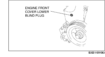
(6) Engine front cover lower blind plug
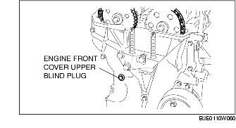
(7) Engine front cover upper blind plug

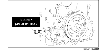
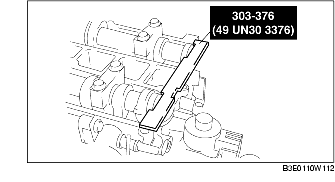
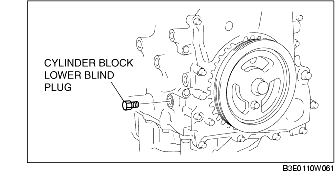
(8) Cylinder block lower blind plug 6. Install the SST as shown in the figure.
7. Turn the crankshaft clockwise the crankshaft is in the No.1 cylinder TDC position (until the balance weight is attached to the SST).
8. Loosen the timing chain.
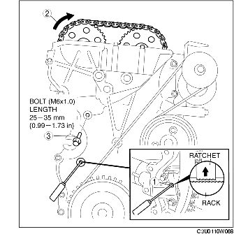
(1) Unlock the chain tensioner ratchet using a suitable screwdriver or equivalent tool.
(2) Turn the exhaust camshaft clockwise using a suitable wrench on the cast hexagon and loosen the timing chain.
(3) Placing the suitable bolt (M6 X 1.0 length 25mm-35mm {0.99-1.37in}) at the engine front cover upper blind plug, secure the chain guide at the position where the tension is released.
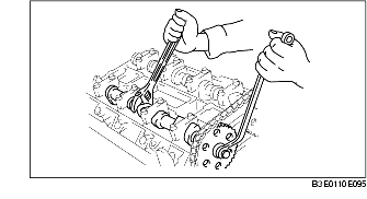
9. Hold the exhaust camshaft using a suitable wrench on the cast hexagon as shown in the figure.
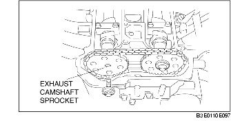
10. Remove the exhaust camshaft sprocket.
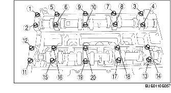
11. Loosen the camshaft cap bolts in 2-3 passes in the order shown in the figure.

Note • The cylinder head and the camshaft caps are numbered to be reassembled in their original position correctly. When removed, keep the caps with the cylinder head they were removed from. Do not mix the caps.
12. Remove the camshaft.
13. Remove the tappet.
14. Select proper adjustment shim.
New adjustment shim = Removed shim thickness + Measured valve clearance - Standard valve clearance (IN: 0.25 mm {0.0098 in}, EX: 0.30 mm {0.0118 in}) Standard [Engine cold] IN: 0.22-0.28 mm {0.0087-0.0110 in} EX: 0.27-0.33 mm {0.0107-0.0129 in}
15. Install the camshaft with No.1 cylinder aligned with the TDC position.
16. Tighten the camshaft cap bolt with the following 2 steps.
Tightening torque (1) 5.0-9.0 N�m {51.0-91.7 kgf�cm, 44.3-79.6 in�lbf} (2) 14.0-17.0 N�m {1.5-1.7 kgf�m, 10.4-12.5 ft�lbf}
17. Install the exhaust camshaft sprocket.
Note • Do not tighten the bolt for the camshaft sprocket during this step. First confirm the valve timing, then tighten the bolt.
18. Install the SST to the camshaft as shown in the figure.
19. Remove the (M6 X 1.0 length 25mm-35mm {0.99-1.37in}) bolt from the engine front cover to apply tension to the timing chain.
20. Turn the crankshaft clockwise until the crankshaft is in the No.1 cylinder TDC position (until the balance weight is attached to the SST).
21. Hold the exhaust camshaft using a suitable wrench on the cast hexagon as shown in the figure.
22. Tighten the exhaust camshaft sprocket lock bolt.
Tightening torque 69-75 N�m {7.1-7.6 kgf�m, 50.9-55.3 ft�lbf} 23. Remove the SST from the camshaft.
24. Remove the SST from the block lower blind plug.
25. Rotate the crankshaft clockwise two turns until the TDC position.
• If not aligned, loosen the crankshaft pulley lock bolt and repeat from Step 14. 26. Apply silicone sealant to the engine front cover upper blind plug.
27. Install the following parts.
(1) Engine front cover upper blind plug

Tightening torque 8.0-11.5 N�m {81.6-117.2 kgf�cm, 70.9-101.7 in�lbf} (2) Cylinder block lower blind plug
Tightening torque 18-22 N�m {1.9-2.2 kgf�m, 14-16 ft�lbf}
(3) New engine front cover lower blind plug
Tightening torque 10-14 N�m {1.1-1.4 kgf�m, 7.4-10.3 ft�lbf}
(4) Cylinder head cover
(5) Ventilation hose
(6) Ignition coils
(7) Engine under cover and splash shield (RH)
(8) Front wheel and tire (RH)
28. Connect the wiring harness.
29. Connect the negative battery cable.
30. Install the battery cover.
31. Install the plug hole plate.
2. Remove the battery cover.
3. Disconnect the negative battery cable.
4. Disconnect the wiring harness.
5. Remove the following parts.
(1) Front wheel and tire (RH)
(2) Engine under cover and splash shield (RH)
(3) Ignition coils
(4) Ventilation hose
(5) Cylinder head cover
(6) Engine front cover lower blind plug
(7) Engine front cover upper blind plug
(8) Cylinder block lower blind plug 6. Install the SST as shown in the figure.
7. Turn the crankshaft clockwise the crankshaft is in the No.1 cylinder TDC position (until the balance weight is attached to the SST).
8. Loosen the timing chain.
(1) Unlock the chain tensioner ratchet using a suitable screwdriver or equivalent tool.
(2) Turn the exhaust camshaft clockwise using a suitable wrench on the cast hexagon and loosen the timing chain.
(3) Placing the suitable bolt (M6 X 1.0 length 25mm-35mm {0.99-1.37in}) at the engine front cover upper blind plug, secure the chain guide at the position where the tension is released.
9. Hold the exhaust camshaft using a suitable wrench on the cast hexagon as shown in the figure.
10. Remove the exhaust camshaft sprocket.
11. Loosen the camshaft cap bolts in 2-3 passes in the order shown in the figure.
Note • The cylinder head and the camshaft caps are numbered to be reassembled in their original position correctly. When removed, keep the caps with the cylinder head they were removed from. Do not mix the caps.
12. Remove the camshaft.
13. Remove the tappet.
14. Select proper adjustment shim.
New adjustment shim = Removed shim thickness + Measured valve clearance - Standard valve clearance (IN: 0.25 mm {0.0098 in}, EX: 0.30 mm {0.0118 in}) Standard [Engine cold] IN: 0.22-0.28 mm {0.0087-0.0110 in} EX: 0.27-0.33 mm {0.0107-0.0129 in}
15. Install the camshaft with No.1 cylinder aligned with the TDC position.
16. Tighten the camshaft cap bolt with the following 2 steps.
Tightening torque (1) 5.0-9.0 N�m {51.0-91.7 kgf�cm, 44.3-79.6 in�lbf} (2) 14.0-17.0 N�m {1.5-1.7 kgf�m, 10.4-12.5 ft�lbf}
17. Install the exhaust camshaft sprocket.
Note • Do not tighten the bolt for the camshaft sprocket during this step. First confirm the valve timing, then tighten the bolt.
18. Install the SST to the camshaft as shown in the figure.
19. Remove the (M6 X 1.0 length 25mm-35mm {0.99-1.37in}) bolt from the engine front cover to apply tension to the timing chain.
20. Turn the crankshaft clockwise until the crankshaft is in the No.1 cylinder TDC position (until the balance weight is attached to the SST).
21. Hold the exhaust camshaft using a suitable wrench on the cast hexagon as shown in the figure.
22. Tighten the exhaust camshaft sprocket lock bolt.
Tightening torque 69-75 N�m {7.1-7.6 kgf�m, 50.9-55.3 ft�lbf} 23. Remove the SST from the camshaft.
24. Remove the SST from the block lower blind plug.
25. Rotate the crankshaft clockwise two turns until the TDC position.
• If not aligned, loosen the crankshaft pulley lock bolt and repeat from Step 14. 26. Apply silicone sealant to the engine front cover upper blind plug.
27. Install the following parts.
(1) Engine front cover upper blind plug
Tightening torque 8.0-11.5 N�m {81.6-117.2 kgf�cm, 70.9-101.7 in�lbf} (2) Cylinder block lower blind plug
Tightening torque 18-22 N�m {1.9-2.2 kgf�m, 14-16 ft�lbf}
(3) New engine front cover lower blind plug
Tightening torque 10-14 N�m {1.1-1.4 kgf�m, 7.4-10.3 ft�lbf}
(4) Cylinder head cover
(5) Ventilation hose
(6) Ignition coils
(7) Engine under cover and splash shield (RH)
(8) Front wheel and tire (RH)
28. Connect the wiring harness.
29. Connect the negative battery cable.
30. Install the battery cover.
31. Install the plug hole plate.
Last edited by Tracker; Aug 25, 2010 at 08:34 PM.
Senior Member
Joined: Jan 2006
Posts: 3,183
Likes: 0
From: Aberdeen, MD
id figure id let you see the work involved instead of just saying "its a service center job", but no valve adjustment is something that dont really have a "service" interval either you need it or you dont


Thread
Thread Starter
Forum
Replies
Last Post
poveglia99
Mazda BT 50 & Pickup Trucks
6
Oct 24, 2014 04:46 PM
goldy
Mazda 323,Mazda 626 & Mazda 929
0
Jan 6, 2006 11:53 AM